1 Introduction
Ethernet is a family of frame-based machine networking
technologies for local area networks (LAN) that defines wiring and signaling
standards for the Physical Layer (PHY) of the OSI networking model (see below)
as well as a common addressing format and a variety of Medium Access Control
(MAC) procedures at the lower part of the Data Link Layer. Ethernet is
standardized under the name IEEE 802.3.
Embedded Ethernet is generally a chip- or chipset-level
implementation of the Ethernet networking standard. By embedding Ethernet into
a device, it becomes endowed with the capacity to communicate remotely via the
existing Internet infrastructure, without using a computer. The device can be
setup as a web server and the user can interact with much of its functionality
though a web page, thus operations such as reading local inputs or
communication packets, actuating local outputs, reading the hardware states,
etc. can all be performed remotely.
This very long distance
machine-to-machine or human-to-machine communication facility which does not
require the deployment of specific infrastructure has made Embedded Ethernet
the most appealing remote control or monitoring solution for a wide variety of
market segments, from Industrial/Home Automation to Medical/Scientific
Equipment, Security Systems, remote media transfer and many others.
2 Ethernet Stack Structure
The Open Systems Interconnection model (OSI model) is a
product of the Open Systems Interconnection effort at the International
Organization for Standardization. It is a method of dividing a communication
system into functional layers, where a layer is a collection of similar
functions that provide services only to the layer above it and receives
services only from the layer below it.
The following table describes the standard OSI model and,
at the rightmost column, (only several of) the corresponding typical Internet
protocols per each layer.
Table 2.1. OSI Model
OSI Model
|
Function
|
|||
Data Unit
|
Layer
|
Description
|
Protocols
|
|
Host layers
|
Data
|
7. Application
|
Network process to application
|
DHCP, HTTP,
SNMP, SMTP,
DNS, FTP
|
6. Presentation
|
Data representation, ecryption and decryption,
convert machine dependent data to machine independent data
|
SSL (when
encryption is used)
|
||
5. Session
|
Interhost communication
|
Sockets, session
establishment in
TCP
|
||
Segments
|
4. Transport
|
End-to-end connections and
reliability, flow control
|
TCP, UDP
|
|
Media layers
|
Packet
|
3. Network
|
Path determination
and logical addressing
|
IP (IPv4, IPv6)
|
Frame
|
2. Data Link
|
Physical addressing
|
IEEE 802.3, ARP
|
|
Bit
|
1. Physical
|
Media, signal and binary transmission
|
IEE 802.3
|
|
3 The LightWeight IP Stack
lwIP (or LightWeight IP) is a low footprint implementation
of the TCP/IP protocol suite that was originally written by Adam Dunkels of the
Swedish Institute of Computer Science and now is being actively developed by a
team of developers distributed world-wide. Since its release, lwIP has spurred
a lot of interest and is today being used in many commercial products. lwIP has
been ported to several platforms and operating systems and can be run either
with or without an underlying OS, which makes it particularly attractive for
resource constrained embedded microcontroller systems.
The focus of the lwIP TCP/IP implementation is to reduce
the RAM usage while still having a full scale TCP. This makes lwIP suitable for
use in embedded systems with several tens of kilobytes of free RAM and room for
around 40 kilobytes of code space (Flash). lwIP features:
• IP (Internet
Protocol) including packet forwarding over multiple network interfaces
• ICMP (Internet
Control Message Protocol) for network maintenance and debugging
• UDP (User
Datagram Protocol) for datagram data
• TCP
(Transmission Control Protocol) with congestion control, RTT estimation ' and
fast recovery/fast retransmit
•
Specialized no-copy API for enhanced performance • Optional Berkeley
socket API
lwIP is freely available (under
a BSD-style license) in C source code format and can be downloaded from the
development homepage http://savannah.nongnu.org/projects/lwip/
4 The AX88796C Ethernet controller and hardwarefixture description
ASIX's AX88796C is an SPI Ethernet controller featuring
low power, a low pin count and variable voltage I/Os for Embedded and
Industrial Ethernet applications. The AX88796C supports two types of interface:
• An 8/16-bit
SRAM-like or Address-Data Multiplex host interface with variable voltage I/O
(1.8/2.5/3.3V), providing a glueless connection to common or high-end MCUs
•
An alternative high speed SPI slave interface for MCUs with SPI master
for simplifying host interface connection The SPI slave interface supports SPI
timing mode 0 and 3, up to 40MHz of SPICLK, variable voltage I/O and
programmable driving strength (8/16 mA)
The AX88796C integrates on-chip Fast Ethernet MAC and PHY,
which is IEEE 802.3/802.3u 10BASET/100BASE-TX compatible, and 14KB of embedded
SRAM for packet buffering to accommodate high bandwidth applications. The
AX88796C offers a wide array of features including support for advanced power
management, high performance data transfer on host interface, IPv4/IPv6
checksum offload engine, HP Auto-MDIX, and IEEE 802.3x and back-pressure flow
control. The small form factor of 64pin LQFP package helps reduce the overall
PCB space. The programming of AX88796C is simple, thus the users can easily
port the software drivers to many embedded systems very quickly.
The chip supports:
• An optional
Ready signal as flow control for SPI packet RX/TX
• IPv4/IPv6 packet
Checksum Offload Engine to reduce CPU loading, including IPv4 IP/TCP/UDP/
ICMP/IGMP and IPv6 TCP/UDP/ICMPv6 checksum generation & check
• VLAN matching
filter
• Twisted pair
crossover detection and correction (HP Auto-MDIX)
• Full duplex with
IEEE 802.3x flow control and half duplex operation with back-pressure flow
control • Auto-polling function
• 10/100Mbps N-way
Auto-negotiation operation
•
An optional EEPROM interface to store MAC address and exhibits various
Advanced Power Management features
For more information, please use the chip datasheet from
the respective manufacturer (www.asix.com.tw).
The present application note
hardware fixture uses as a reference hardware item the AX88796C SMDK2440 board
available from ASIX. External interface pins are available via headers (Figure
4.1 (p. 6) ) to connect to any type of hardware. Please consult the
manufacturer specifications for more information.
Figure 4.1. AX88796C

AX88796C SMDK2440 board AX88796C
SMDK2440 board
Front side Back
side
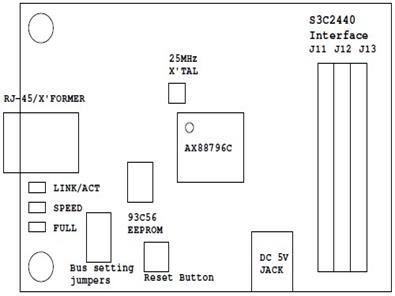
Figure 4.2 (p. 6) depicts the layout of the major
components on the ASIX development board:
Figure 4.2. AX88796C layout
The connectivity between the ASIX development board and
the EFM32 STK is achieved following the connections described in the following
table:
Table 4.1. Pin Connections
EFM32G890F128
|
STK expansion header pin
|
Function
|
AX88796C board header
|
Pin
|
Function
|
|
-
|
18
|
USB 5V
|
J11
|
31
|
Vcc
|
|
-
|
1
|
GND
|
J13
|
1
|
GND
|
|
EFM32G890F128
|
STK expansion header pin
|
Function
|
AX88796C board header
|
Pin
|
Function
|
|
PD0
|
4
|
SPI_TX
|
J13
|
2
|
SD0/S MOSI
|
|
PD1
|
6
|
SPI_RX
|
J13
|
3
|
SD1/S MISO
|
|
PD2
|
8
|
SPI_CLK
|
J12
|
34
|
S CLK0
|
|
PD3
|
10
|
SPI_CS
|
J11
|
2
|
CSN/SS0
|
|
PD4
|
12
|
RESET
|
J11
|
30
|
RESETN
|
|
PB12
|
13
|
INT
|
J11
|
18
|
IRQ
|
The USB 5V connection is optional and should only be used
if the user wants to power the ASIX board using the STK. The board can also be
supplied using a 5V regulated supply connected to the DC 5V JACK (Figure 4.2
(p. 6) ). To select between these two supplies jumper J4 should be placed as
described in Table 4.2 (p. 7) . The Vmcu power line can also be used to supply
the board instead of the USB 5V but it is recommended to use the USB 5V for
higher current sourcing.
Additionally, on the ASIX development board, suitable 4.7
KOhm resistors should be assembled in the R22, R1, R2 and R26 positions to
ensure pulling the SPI bus signals high when inactive.
Table 4.2. Jumper Configuration
Jumper
|
Position
|
J2
|
1-2
|
J3
|
1-2
|
J4
|
not mounted
|
J5
|
1-2 closed and 3-4 open
|
J6
|
1-2 for DC_JACK supply or 2-3 for USB 5V supply
|
J8
|
1-2
|
J9
|
1-2
|
5 EFM32 Implementation
This example application demonstrates the operation of the
EFM32G890F128 running the leIP TCP/IP stack and connecting to the AX88796C
Ethernet controller. The project can be configured to use Static IP or DHCP. It
implements a minimal embedded http web server which serves a web page
displaying the current EFM MCU temperature and number of times the page was
refreshed (the page is being automatically refreshed every 5 seconds).
In order to run the example code, follow the next steps:
1. Connect the EFM32-Gxxx-STK
2. Compile and build the
project code
3. Download the code in the MCU
4. Start the application
5.
Run the example by typing the board's IP in a web browser. The board
will serve a web page (Figure 5.1 (p. 8) )
Figure 5.1. Web Page

The "number of times this page was refreshed"
counter will increment automatically every 5 seconds.
The software can be configured to use either static IP or
DCHP where it needs to be connected to a DHCP server to provide an IP address.
To select between them the LWIP_DHCP
define in lwipopts.h should be
used. Depending on the value of this macro the IP configuration function (lwIPInit(const unsigned char *pucMAC,
unsigned long ulIPAddr, unsigned long ulNetMask, unsigned long ulGWAddr,
unsigned long ulIPMode)) will be called with different parameters on main.
The IP address will be shown in
the STK LCD. Since there are not enough characters to show the full IP address it cycles between the 4 IP fields showing them on the top right corner of the LCD while an X marks which IP field the number corresponds to (Figure 5.2 (p.9) ).
Figure 5.2. IP on LCD
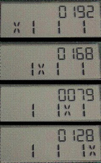
Figure 5.2. IP on LCD

No comments:
Post a Comment